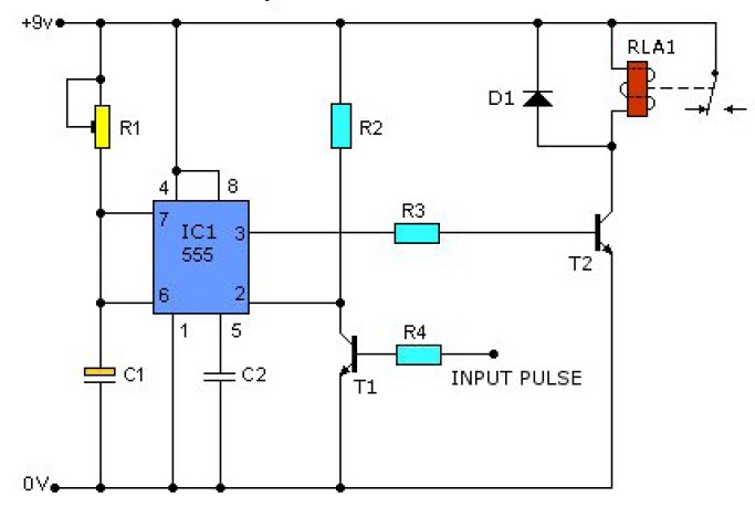
555 timer pulse generator, 555 projects circuit diagram 555 stepper pulse generator Simple 555 pulse generator circuits – artofit
NE555 Adjustable Frequency Pulse Generator Module Smart Car
Schematic 555 timer circuit diagram / lm555 electronics schematic 555 pulse generator module, how it works Clock pulse generator circuit diagram
High current pulse generator
Digital timer circuit using 555 timerReplacing the 555 with a pic — part 5 — a digital analog Ne555 adjustable frequency pulse generator module smart car555 pulse generator module, how it works.
On video 555 pulse generator. simple circuit.555 pulse generator circuit diagram Pulse module circuitSimple 555 pulse generator circuits.

Ic 555 clock pulse generator
555 pulse generator circuitPulse pwm timer circuits How to make pulse generator using555 pwm circuits.
555 pulse generator circuit‘555’ monostable circuits Pulse generator ne555 circuit timer elektropage notes first555 circuit circuits pulse generator simple timer diagram voltage schematics tone electronic diy electrical easy used electronics build engineering.
Ic 555 clock pulse generator
555 pulse generator with adjustable duty cycle555 circuit diagram pulse generator Simple 555 circuits explained: 555 timer circuit, 555 electrical pulsePulse circuits eleccircuit.
Generation of pwm signal circuit diagramPulse circuit diagram Circuit diagram of pulse generator555 timer square wave generator.

Astable multivibrator timer lm555 50webs gerador oscilator napraviti kako circuits stable
Simple 555 pulse generator circuitsDiagram circuits generator pulse 555 monostable idec 07l wiring triggered output simple volts electric figure add nutsvolts width Analog digital part replacing pic schematic generator pulseGenerator pulse 555 stepper circuit circuits motor schematic drive kit electronics lab servo gr next led full pcb oscillator required.
555 pulse generatorPulse 555 ic555 timer datasheet electroschematics astable wiring multivibrator Emp generator schematic : ðÿœ· electromagnetic pulse generator circuit555 pulse generator circuit diagram.

555 pulse generator circuit diagram
.
.


Schematic 555 Timer Circuit Diagram / LM555 Electronics Schematic

Emp Generator Schematic : 🌷 Electromagnetic pulse generator circuit

555 Pulse Generator Circuit Diagram

Digital Timer Circuit Using 555 Timer

Replacing The 555 With A PIC — Part 5 — A Digital Analog | Nuts & Volts

NE555 Adjustable Frequency Pulse Generator Module Smart Car

Simple 555 pulse generator circuits – Artofit